Storage and Disposal of Radioactive Waste
- Radioactive waste is stored so as to avoid any chance of radiation exposure to people, or any pollution.
- The radioactivity of the waste decays with time, providing a strong incentive to store high-level waste for about 50 years before disposal.
- Disposal of low-level waste is straightforward and can be undertaken safely almost anywhere.
- Storage of used fuel is normally under water for at least five years and then often in dry storage.
- Deep geological disposal is widely agreed to be the best solution for final disposal of the most radioactive waste produced.
Most low-level radioactive waste (LLW) is typically sent to land-based disposal immediately following its packaging for long-term management. This means that for the majority (~90% by volume) of all of the waste types produced by nuclear technologies, a satisfactory disposal means has been developed and is being implemented around the world.
For used fuel designated as high-level radioactive waste (HLW), the first step is storage to allow decay of radioactivity and heat, making handling much safer. Storage of used fuel may be in ponds or dry casks, either at reactor sites or centrally. Beyond storage, many options have been investigated which seek to provide publicly acceptable, safe, and environmentally sound solutions to the final management of radioactive waste. The most widely favoured solution is deep geological disposal. The focus is on how and where to construct such facilities.
Used fuel that is not intended for direct disposal may instead be reprocessed in order to recycle the uranium and plutonium it contains. Some separated liquid HLW arises during reprocessing; this is vitrified in glass and stored pending final disposal.
Intermediate-level radioactive waste (ILW) that contains long-lived radioisotopes is also stored pending disposal in a geological repository. In the USA, defence-related transuranic (TRU) waste – which has similar levels of radioactivity to some ILW – is disposed of in the Waste Isolation Pilot Plant (WIPP) deep geological repository in New Mexico. A number of countries dispose of ILW containing short-lived radioisotopes in near-surface disposal facilities, as used for LLW disposal.
Some countries are at the preliminary stages of their consideration of disposal for ILW and HLW, whilst others, in particular Finland, have made good progress. Finland's Onkalo repository is undergoing final licence review. It will be the first deep geological repository for the disposal of used fuel from civil reactors.
The following table sets out the commonly accepted disposal options. When considering these, it should be noted that the suitability of an option or idea is dependent on the wasteform, volume, and radioactivity of the waste. As such, waste management options and ideas described in this section are not all applicable to different types of waste.
Commonly-accepted disposal options
| Option | Suitable waste types | Examples |
| Near-surface disposal at ground level, or in caverns below ground level (at depths of tens of metres) | LLW and short-lived ILW |
|
| Deep geological disposal (at depths between 250m and 1000m for mined repositories, or 2000m to 5000m for boreholes) |
Long-lived ILW and HLW (including used fuel) |
|
Additional ideas have also been considered and discounted in the past (see section on Other ideas for disposal below, and information paper on International Nuclear Waste Disposal Concepts).
Near-surface disposal
The International Atomic Energy Agency (IAEA) definitionb of this option is the disposal of waste, with or without engineered barriers, in:
- Near-surface disposal facilities at ground level. These facilities are on or below the surface where the protective covering is of the order of a few metres thick. Waste containers are placed in constructed vaults and when full the vaults are backfilled. Eventually they will be covered and capped with an impermeable membrane and topsoil. These facilities may incorporate some form of drainage and possibly a gas venting system.
- Near-surface disposal facilities in caverns below ground level. Unlike near-surface disposal at ground level, where the excavations are conducted from the surface, shallow disposal requires underground excavation of caverns. The facility is at a depth of several tens of metres below the Earth's surface and accessed through a drift.
The term near-surface disposal replaces the terms 'shallow land' and 'ground disposal', but these older terms are still sometimes used when referring to this option.
These facilities will be affected by long-term climate changes (such as glaciation) and this effect must be taken into account when considering safety, as such changes could disrupt these facilities. This type of facility is therefore typically used for LLW and short-lived ILW with half-lives of up to 30 years.
Near-surface disposal facilities at ground level are currently in operation in:
- UK – LLW Repository at Drigg in Cumbria operated by UK Nuclear Waste Management (a consortium led by AECOM with Studsvik UK, Serco, and Orano) on behalf of the Nuclear Decommissioning Authority.
- Spain – El Cabril LLW and ILW disposal facility operated by ENRESA.
- France – Centre de l'Aube operated by Andra.
- Japan – LLW Disposal Center at Rokkasho-Mura operated by Japan Nuclear Fuel Limited.
- USA – five LLW disposal facilities: Texas Compact facility near the New Mexico border, operated by Waste Control Specialists; Barnwell, South Carolina operated by EnergySolutions; Clive, Utah (EnergySolutions); Oak Ridge, Tennessee (EnergySolutions); and Richland, Washington – operated by American Ecology Corporation.
In Brazil, construction of the Centena near-surface repository for low- and intermediate-level waste is planned to begin in 2026, which would be the first radioactive waste repository in Latin America.
Near-surface disposal facilities in caverns below ground level are currently in operation in:
- Sweden – the SFR final repository for short-lived radioactive waste at Forsmark, where the depth of the facility is 50m under the Baltic seabed – operated by the Swedish Nuclear Fuel and Waste Management Company (SKB)c.
- Finland – an underground repository at Olkiluoto for LLW and ILW has been in operation since 1992. A similar facility at Loviisa was commissioned in 1997. The depth of these is about 100 metresd.
Deep geological disposal
The long timescales over which some waste remains radioactive has led to the idea of deep disposal in underground repositories in stable geological formations. Isolation is provided by a combination of engineered and natural barriers (rock, salt, clay) and no obligation to actively maintain the facility is passed on to future generations. This is often termed a 'multi-barrier' concept, with the waste packaging, the engineered repository, and the geology all providing barriers to prevent the radionuclides from reaching humans and the environment. In addition, deep groundwater is generally devoid of oxygen, minimising the possibility of chemical mobilization of waste.
Deep geological disposal is the preferred option for nuclear waste management in most countries, including Argentina, Australia, Belgium, Canada, Czech Republic, Finland, France, Japan, the Netherlands, Republic of Korea, Russia, Spain, Sweden, Switzerland, the UK, and the USA. Hence, there is much information available on different disposal concepts; a few examples are given here. The only purpose-built deep geological repository that is currently licensed for disposal of nuclear material is the Waste Isolation Pilot Plant (WIPP) in the USA, but it does not have a licence for disposal of used fuel or HLW. Plans for disposal of spent fuel are particularly well advanced in Finland, as well as Sweden, France, and the USA, though in the USA there have been political delays. In Canada and the UK, deep disposal has been selected and the site selection processes have commenced.
Mined repositories
The most widely proposed deep geological disposal concept is for a mined repository comprising tunnels or caverns into which packaged waste would be placed. In some cases (e.g. wet rock) the waste containers are then surrounded by a material such as cement or clay (usually bentonite) to provide another barrier (called buffer and/or backfill). The choice of waste container materials and design, as well as the buffer/backfill material varies depending on the type of waste to be contained and the nature of the host rock-type available.
Excavation of a deep underground repository using standard mining or civil engineering technology is limited to accessible locations (e.g. under land or nearshore), to rock units that are reasonably stable and without major groundwater flow, and to depths of between 250m and 1000m. The contents of the repository would be retrievable in the short term, and if desired, longer-term.
The Swedish proposed KBS-3 disposal concepte uses a copper container with a steel insert to contain the spent fuel. After placement in the repository about 500 metres deep in the bedrock, the container would be surrounded by a bentonite clay buffer to provide a very high level of containment of the radioactivity in the spent fuel over a very long time period. In June 2009, the Swedish Nuclear Fuel and Waste Management Company (SKB) announced its decision to locate the repository at Östhammar (Forsmark).
Finland's repository programme is also based on the KBS-3 concept. Spent nuclear fuel packed in copper canisters would be embedded in the Olkiluoto bedrock at a depth of around 400 metres. The country's nuclear waste management company, Posiva Oy, submitted its operating licence application in December 2021. Its construction was licensed in November 2015, and the encapsulation plant has been tested with dummy fuel.
The deposits of native (pure) copper in the world have proven that the copper used in the final disposal container can remain unchanged inside the bedrock for extremely long periods, if the geochemical conditions are appropriate (low levels of groundwater flow). The findings of ancient copper tools, many thousands of years old, also demonstrate the long-term corrosion resistance of copper, making it a credible container material for long-term radioactive waste storage.
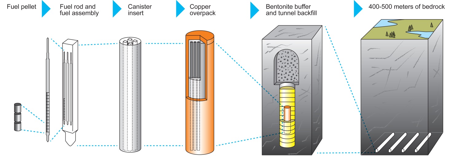
Multi-barrier disposal concept (Image: Posiva)
Deep boreholes
As well as mined repositories, which have been the focus of most international efforts so far, deep borehole disposal has been considered as an option for geological isolation for many years, including original evaluations by the US National Academy of Sciences in 1957 and more recent conceptual evaluations. In contrast to recent thinking on mined repositories, the contents would not be retrievable.
The concept consists of drilling a borehole into basement rock to a depth of up to about 5000 metres, emplacing waste canisters containing used nuclear fuel or vitrified radioactive waste from reprocessing in the lower 2000 metres of the borehole, and sealing the upper 3000 metres of the borehole with materials such as bentonite, asphalt or concrete. The disposal zone of a single borehole could thus contain 400 steel canisters each 5 metres long and one-third to half a metre in diameter. The waste containers would be separated from each other by a layer of bentonite or cement.
Boreholes can be readily drilled offshore (as described in the section below on sub seabed disposal) as well as onshore in both crystalline and sedimentary host rocks. This capability significantly expands the range of locations that can be considered for the disposal of radioactive waste.
Deep borehole concepts have been developed (but not implemented) in several countries, including Denmark, Sweden, Switzerland, and the USA. Compared with deep geological disposal in a mined underground repository, placement in deep boreholes is considered to be more expensive for large volumes of waste. This option was abandoned in countries such as Sweden, Finland, and the USA, largely on economic grounds. The borehole concept remains an attractive proposition for the disposal of smaller waste forms including sealed radioactive sources from medical and industrial applicationsf.
An October 2014 US Department of Energy (DOE) report said: “Preliminary evaluations of deep borehole disposal indicate a high potential for robust isolation of the waste, and the concept could offer a pathway for earlier disposal of some wastes than might be possible in a mined repository.” In January 2016 the DOE commissioned a team led by Battelle to drill a 4880-metre test borehole into crystalline basement rock in North Dakota, but the project was later scrapped following local opposition.
In 2021 the US company Deep Isolation contracted with Slovenia’s radioactive waste management organization ARAO to conduct a feasibility study on the use of deep boreholes to dispose of the country’s spent research reactor fuel. It has conducted feasibility studies also for Fermi Energia in Estonia and the Electric Power Research Institute in USA. In 2024-2025 Deep Isolation completed a two-year US Department of Energy-funded research project validating the corrosion resistance and structural integrity of its canister system.
As part of a pilot study, the IAEA have provided technological and engineering support for the construction and implementation of borehole disposal facilities in Malaysia and Ghana. Preparatory work for the start of construction of the Malaysian borehole is in its final stages, with the facility expected to be operational in 2023. The facility is situated at Nuclear Malaysia's main complex in Selangor. Ghana is also in the advanced stage of implementing its borehole project, with construction expected to begin as soon as the licensing review process is completed. The site will be managed by Ghana Atomic Energy Commission and based in the Accra region. The IAEA hope that these projects will provide a model for other countries to follow.
Mined repositories – development examples
Boom clay & Opalinus clay, Europe
The Belgian disposal concept proposes that spent fuel and HLW is placed in high integrity steel containers and then emplaced in excavated tunnels 230 metres deep within a ductile (self-sealing) clayg – the Boom clay. The very low permeability of the clay leads to virtually no groundwater flow over long time periods. Waste would be backfilled with excavated clay or, alternatively, could be emplaced into unlined secondary tunnels where the clay would be allowed to 'creep' into contact with the waste containers. Similar systems have been proposed in the Netherlands and, using less plastic clays, in France and Switzerlandh (Opalinus clay). Clay is generally suitable for heat-generating HLW, and the OECD Nuclear Energy Agency has a ‘Clay Club’ researching this.
The French radioactive waste disposal agency, Andra, is designing a deep geological repository in clays near Bure in eastern France. This will be for disposal of vitrified HLW and long-lived ILW. The repository is designed to operate at up to 90ºC, which is likely to be reached about 20 years after emplacement.
Yucca Mountain, USA
At the end of 1987, the Nuclear Waste Policy Act was amended to designate Yucca Mountain, located in the remote Nevada desert, as the sole US national repository for spent fuel and HLW from nuclear power and military defence programs. An application by the US DOE to construct the repository was submitted in June 2008.
The repository would exist 300 metres underground in an unsaturated layer of welded volcanic tuff rock. Waste would be stored in highly corrosion-resistant double-shelled metal containers, with the outer layer made of a highly corrosion-resistant metal alloy, and a structurally strong inner layer of stainless steel. Since the geological formation is essentially dry, it would not be backfilled but left open to some air circulation. Drip shields made of corrosion-resistant titanium would cover the waste containers to divert possible future water percolation and provide protection from possible falling rock or debris. Containment relies on the extremely low water table, which lies approximately 300 metres below the repository, and the long-term durability of the engineered barriers.
The project has experienced many delays since its inception and following the 2009 presidential election the Barack Obama administration decided to cancel iti. However, in June 2010 the Nuclear Regulatory Commission's Atomic Safety and Licensing Board (ASLB) rejected the DOE's motion to withdraw the licence application, and in August 2013 the federal Appeals Court ordered the NRC to resume its review of the DOE's application for a licence to construct and operate the Yucca Mountain repository. The final volumes of the NRC’s safety evaluation report were published early in 2015, which contain the agency's technical review of safety of the repository. In May 2016 the NRC released its final supplement to the US DOE's environmental impact statement on the proposed Yucca repository. Both the environmental impact assessment and the NRC's experts established that the repository design would prove safe for one million years.
Disposal in layered salt strata or domes
Geological salt environments have a very low rate (perhaps even an absence) of groundwater flow and feature gradual self-sealing of the excavations due to creep of the salt, which is plastic. Salt is generally suitable for heat-generating HLW, and the OECD Nuclear Energy Agency has a ‘Salt Club’ researching this.
The Waste Isolation Pilot Plant (WIPP)j in New Mexico for defence transuranic wastes (long-lived ILW) has been operational since 1999. For this repository natural rock salt is excavated from a Permian layer several metres thick, between other types of rock, 650 metres below ground level. The wastes placed in these excavations contain large volumes of long-lived ILW, usually in steel drums. These are then placed on pallets and stowed in excavated rooms or caverns. The salt is plastic and will eventually seal the wastes and isolate them permanently. Containment of the radionuclides in the wasteform mostly relies on the almost complete absence of water flow in the salt. To date over 90,000 cubic metres of ILW has been disposed of at WIPP.
Salt environments are also available in northern Germany and the Netherlands although these are salt domes rather than bedded formations. In Germany, the former salt mines at Asse and Morsleben have been used for LLW and ILW disposal though this has now been suspended. The decommissioning process is now being investigated to determine the method for backfilling and sealing the repository.
Following an exhaustive site selection process the state government of Lower Saxony in 1977 declared the salt dome at Gorleben to be the location for a German national centre for disposal of radioactive wastes. Some €1.5 billion was spent over 1979 to 2000 researching the site. Work then stopped due to political edict, but resumption of excavation was approved following a change of government in 2009. Following a new law in early 2017, Gorleben was then considered one possible site for geological disposal of HLW. However, in September 2020 Germany launched a new search for a disposal site, naming 90 possible locations (but not Gorleben).
Nirex Phased Disposal Concept, UK
The UK's Nirex Phased Disposal Concept (or Phased Geological Disposal Concept) has been developed for relatively large volumes of ILW and LLW, usually cemented into stainless steel containersk. These containers would be emplaced into a repository in a host rock environment below the water table. The waste would be monitored and remain retrievable and the groundwater managed to prevent contact with the wastes, until such a time that the repository is sealed. When this happens, the waste will be surrounded (backfilled) by specially formulated cement and the repository allowed to resaturate. The cement would provide a long-lasting alkaline environment that contributes to containment of the waste by preventing many radionuclides from dissolving in the groundwater. Similar cement-based schemes for ILW disposal have been proposed in France, Japan, Sweden and Switzerland.
Multinational repositories
Not all countries are adequately equipped to store or dispose of their own radioactive waste. Some countries are limited in area, or have unfavourable geology, and therefore siting a repository and demonstrating its safety could be challenging. Some smaller countries may not have the resources to take the proper measures on their own to ensure adequate safety and security, or they may not have enough radioactive waste to make construction and operation of their own repositories economically feasible.
It has been suggested that there could be multinational or regional repositories located in a willing host country that would accept waste from several countries. They could include, for example, use by others of a national repository operating within a host country, or a fully international facility owned by a private company operated by a consortium of nations or even an international organization. However, for the time being, many countries would not accept nuclear waste from other countries under their national laws. National policies towards radioactive waste management are listed in National Radioactive Waste Management Appendix 2: National Policies & Funding and the information paper on International Nuclear Waste Disposal Concepts.
Deep geological repository projects
Construction Underway
| Location | Commissioning date | Organisation Responsible | Stage of process |
| Onkalo, Finland | 2026 | Construction complete. Encapsulation plant tested with dummy fuel. Awaiting operating licence from STUK. |
Planned projects with selected site
| Location | Commissioning date | Organisation Responsible | Stage of process |
| Canada | 2040s | NWMO | Site selected in November 2024: Wabigoon Lake Ojibway Nation and Township of Ignace, Ontario. Initial project description submitted to regulators in January 2026. |
| France, Cigéo | 2050 | In July 2022 the French official journal published the decree recognising the public utility of Cigéo. Construction licence application submitted in January 2023. ASNR issued a favourable opinion in December 2025. Public inquiry scheduled for the second half of 2026. |
|
| Russia, Krasnoyarsk | tbc | NORWM | Underground Research Laboratory under construction. Construction of DGR will begin after research period. |
| Sweden, Forsmark | 2030-2032 | SKB | Licence application for construction approved in September 2022. Surface works underway. Application for underground excavation submitted in January 2025. |
| Switzerland, Nördlich Lägern | 2050 | Swiss Nuclear | General licence application submitted to the federal government in November 2024. Federal Council decision expected around 2029, parliamentary decision around 2030, optional referendum 2031. |
Proposed projects
| Location | Commissioning date | Organisation Responsible | Stage of process |
| China | 2050+ | CNNC | Construction process of URL to test the suitability of Besuha region. If successful, an underground repository will be built near the laboratory by 2050). |
| Czech Republic | 2065 | SÚRAO | Site selection by 2030. |
| Germany | tbc | BGR | Site selection ongoing. BGE proposed narrowing to 5-10 sites for surface exploration by end of 2027. |
| Hungary | 2030 | PURAM | Site selection process is expected to be completed by 2032. |
| India | tbc | AEC | Plans are focused on the northwest Rajasthan region |
| Japan | 2050 | NUMO | Literature survey completed November 2024 for Suttu and Kamoenai in Hokkaido. NUMO recommended proceeding to overview survey (drilling). Hokkaido governor has voiced opposition. |
| Norway | tbc | NND | In December 2025, 22 municipalities were invited to express interest in hosting nuclear waste disposal facilities. |
| Slovakia | tbc | JAVYS | Detailed site investigations ongoing at prospective localities. |
| United Kingdom | 2040 | NDA | Site selection launched in 2018. Three community partnerships formed; Theddlethorpe partnership ended in 2025. Mid Copeland and South Copeland remain active. |
| USA | Suspended | USA DOE | A solution to the permanent disposal of spent nuclear fuel (SNF) in the United States is currently stalled. |
Interim waste storage and transport
Specially designed interim surface or sub-surface storage waste facilities are currently used in many countries to ensure the safe storage of hazardous radioactive waste pending the availability of a long-term disposal option. Interim storage facilities are generally used for ILW and HLW, including used nuclear fuel from reactors.
Storage ponds
Storage ponds at reactors, and those at centralized facilities such as CLAB in Sweden, are 7-12 metres deep to allow the racked fuel assemblies to be covered by several metres of water. The fuel assemblies are typically about 4 m long and standing on end. The multiple racks are made of metal with neutron absorbers incorporated in it. The circulating water both shields and cools the fuel. These pools are robust constructions made of thick reinforced concrete with steel liners. Ponds at reactors may be designed to hold all the used fuel for the life of the reactor, but usually the design assumes some removal of cooled fuel for reprocessing or to dry storage.
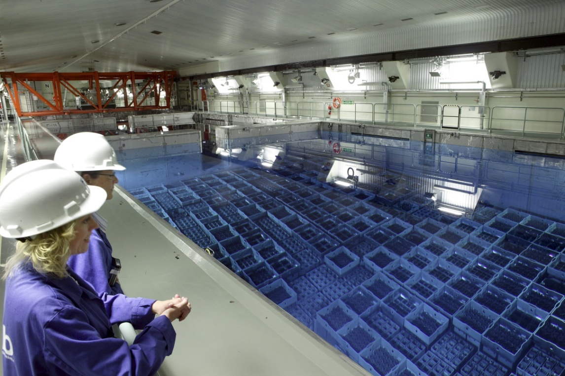
Central Interim Storage Facility (CLAB), Sweden. Image: SKB
Dry storage
Some storage of fuel assemblies which have been cooling in ponds for at least five years is in dry casks or vaults, typically with air circulation inside concrete shielding. Dry storage has been used at US nuclear power plants since 1986, and at least one-third of the total US used fuel is now in dry storage casks. Facilities are at most of the nuclear power plant sites (including some closed ones). As of the end of 2019, 3203 casks had been loaded at 72 interim spent fuel storage installations (ISFSIs) in the USA. Transfer from wet storage to dry casks at a power plant site may use special shielded transfer casks, which are less robust than those used for transport beyond the site. Casks may contain a sealed canister which can be transferred from one kind of cask to another.
Multi-purpose canisters
Sealed multi-purpose canisters (MPCs), also called dual-purpose canisters (DPCs), each holding up to 89 fuel assemblies with inert gas, are commonly used for transporting, storing and eventual disposal of used fuel. MPCs are contained inside robust overpacks – metal for transport, or mainly concrete for storage. Each MPC, constructed using 13 mm welded stainless steel with a secure lid and internal fuel basket to hold and keep the fuel assemblies separate, is designed for up to 45 kW heat load. MPCs have standard external dimensions and the number of fuel assemblies actually loaded into one depends on their characteristics. Some are double-walled (DWC), with helium in between the layers. Once an MPC is loaded the contents should never need to be handled again.
The IAEA publishes radioactive material transport regulations – notably Regulations for the Safe Transport of Radioactive Material, IAEA Safety Standards Series No. SSR-6 (Rev.1).
Holtec’s MPC contains a 68-cell fuel basket for BWR fuel, a 24-cell flux-trap, or a 32-cell non-flux trap fuel basket for PWR fuel. Some have neutron-absorbing Metamic-HT fuel baskets and liners with high thermal conductivity, enabling relatively-hot three-year-old spent fuel to be placed in them. Since 2013 Holtec also makes double-walled canisters (DWCs) for the UK and Ukraine, with the same standard external dimensions.
High-capacity MPCs are able to hold 37 PWR or 87-89 BWR fuel assemblies. Others take only 12 PWR or 32 BWR fuel assemblies. With some small canisters – 4 PWR/9BWR – four can be fitted into a standard transport cask. Orano has a large canister design holding 21 PWR or 44 BWR fuel assemblies.
Storage casks and systems
For storage, each MPC is enclosed in a ventilated storage module or overpack made of concrete and steel. These are commonly standing on the surface, about 6 metres high, cooled by air convection, or they may be horizontal in banks, or vertical and below grade, with just the tops showing. The modules are robust and provide full shielding. At a nuclear power plant, a shielded transfer cask is used to move the MPC from the used fuel pool to a storage module. Holtec’s transfer casks for onsite use are called HI-TRAC.
A free-standing above-ground system is Holtec’s HI-STORM 100, which accommodates a variety of sealed stainless steel MPCs vertically inside ventilated concrete and steel overpacks standing on a concrete pad. The 165-tonne overpack has 65 cm of concrete inside steel casing for shielding. This system is used at many US plants. A below-ground variant is HI-STORM 100U, and a more sophisticated version of this is Holtec’s HI-STORM UMAX storage system, which is already deployed at two US nuclear power plant sites, and proposed for the HI-STORE CIS facility in New Mexico (see below). HI-STORM UMAX stores the canisters containing used fuel in ventilated vertical steel and concrete cavity enclosure containers 5 metres high below ground, with massive lids at ground level. The containers are set up in a 7.6 m deep excavation and low-strength concrete grout is backfilled around them. The final half metre of fill is a reinforced concrete pad. Seismic tolerance is about 2000 Gal.
An above-ground horizontal system is Orano’s NUHOMS HSM-H system, used by 20 of the 67 ISFSIs at US nuclear plants. The used fuel is sealed in 15 mm thick stainless steel dry storage canisters which are then moved in horizontal shielded transfer casks to large horizontal storage modules, with each hole 5 m long and 2 m diameter. Orano claims better heat distribution in these than vertical systems, using conduction more than convection, and also points to no gaps between modules being very safe seismically (1500 Gal) and radiologically. Each canister holds 32-37 PWR fuel assemblies or 61-69 BWR assemblies, in helium. Orano plans to have a US-licensed transport cask for NUHOMS by 2020, and meanwhile it has one for high burn-up fuel. NUHOMS horizontal storage can accommodate a variety of canister designs, and the Orano NUHOMS canisters are compatible with other, e.g. Holtec, vertical storage systems.
In July 2017 the US Nuclear Regulatory Commission granted Orano TN certification for its NUHOMS Extended Optimized Storage (EOS) dry used fuel storage system. The system is designed for high burn-up fuel management and reactors in shutdown phase. The large NUHOMS EOS dry shield canisters hold 37 PWR or 89 BWR fuel assemblies. These can be transferred in the EOS TC series transfer cask and stored in NUHOMS EOS HSM concrete modules.
Germany’s Gesellschaft für Nuklear-Service mbH (GNS), set up in 1977 and owned by the country's four nuclear utilities, is both an operator of waste storage and supplier of two types of cask. The main type are CASTOR casks, more than 1000 of which are used in Germany alone for transport and interim storage of spent fuel and HLW. The cask body provides full shielding and allows loading after very short cooling times of high burn-up fuel, and they are closed with two lids. GNS’s CONSTOR casks are similar but with concrete in the walls and designed for cooler fuels.
A large canister HI-STORM FW storage module is a flood- and wind-resistant version with high seismic tolerance – 1.2 Gal. It holds 37 PWR assemblies, or 89 BWR ones, or 31 VVER-1000 ones, with maximum heat load 46 kW. The HI-STORM 190 is the VVER version of the HI-STORM FW. These canisters can hold damaged fuel in special failed fuel containers.
A new large storage cask is HI-STORM MIC (mega-impact capable) designed with EDF Energy in the UK and having a 100-year design life. It uses a double-walled MPC, and is heavily shielded.
According to the Interim Storage Partners (ISP) website, there were over 460 NAC and 1265 Orano TN casks storing spent fuel at both operating and decommissioned US nuclear plants as of June 2019.
A collection of casks or modules comprises an independent spent fuel storage installation (ISFSI), which in the USA is licensed separately from any associated power plant, and is for interim storage only. About one-third of US used fuel is stored thus.
Recognising that long-term management options, specifically for ILW and HLW, may require significant time to be achieved, interim storage arrangements may need to be extended beyond the time periods originally envisaged.
An indication of the scale of dry storage is that the market for dry storage casks in the Americas, where there is the highest demand, was estimated to be worth approximately $1 billion in 2020.
Some countries, including Australia, Belgium, the Netherlands, Germany, Italy, and Switzerland also place LLW in interim storage, although most LLW is typically sent directly to land-based near-surface disposal facilities (see section above on Near-surface disposal).
ISFSI systems in use
Many US nuclear power plants, both operational and decommissioned, have independent spent fuel storage installations (ISFSIs).
In the USA a large ISFSI is proposed in Texas, using Orano’s NUHOMS system for up to 40,000 tonnes of used fuel. Waste Control Specialists (WCS) applied for a licence for the facility in April 2016, and in March 2018 WCS and Orano USA announced a joint venture – Interim Storage Partners (ISP) – to complete licencing the project. The NRC granted a licence in September 2021, though this was subsequently challenged in court. In June 2025 the US Supreme Court ruled that the challengers lacked standing, upholding the NRC’s licensing authority.
The HI-STORE consolidated interim storage (CIS) facility was proposed in New Mexico by Holtec International for the Eddy Lea Energy Alliance. The NRC granted a licence in May 2023 for up to 8680 tonnes of uranium in used fuel. However, Holtec cancelled the project in 2025, citing state opposition to the facility.
Zwilag’s ZZL in Switzerland and Ahaus and Gorleben in Germany are examples of operating long-term above-ground central interim dry storage for HLW.
Ukraine’s Central Spent Fuel Storage Facility (CSFSF), commissioned in December 2023, uses a Hi-STORM 190 ventilated storage system and Hi-STAR 190 casks for transport to the site. Ukraine requires storage to be in double-wall canisters (DWCs), and these are also used at Sizewell in the UK, giving an increased service life. In Ukraine, Holtec is establishing a centre for supply of dry storage and transport systems to the country's 15 operating reactors and possibly other VVERs around the world.
Lithuania is using GNS CONSTOR M2 dry storage containers at Ignalina, each holding about 90 RBMK fuel assemblies. Bulgaria is also using 270 CONSTOR casks for VVER-440 fuel. CONSTOR casks are robust steel casks with concrete in the walls and three lids, cost-optimized for interim storage of spent fuel which has cooled. They are portable though evidently not designed for shipping used fuel. They are not ventilated and may have a concrete overpack.
Japan’s Federation of Electric Power Companies of Japan (FEPC) aims to develop an all-aluminum, thinner and lighter basket for a concrete cask that would be capable of storing more spent fuel assemblies at temperatures of up to 400°C. It wants to have the design ready for deployment by the mid-2020s. Most dry storage casks require fuel to be cooled in ponds until the temperature drops to about 250°C.
Casks for deep borehole disposal
Deep Isolation has contracted with NAC International to design and supply corrosion-resistant casks 23 to 31 cm diameter and 4.3 m long, each holding one used fuel assembly.
Transport casks
Used fuel assemblies are shipped in 'Type B' casks which are shielded with steel, or a combination of steel and lead, and can weigh up to 110 tonnes when empty. They contain their highly radioactive payload safely during transport, and may hold from 6 to 24 tonnes of used fuel. Some information on transport of used fuel is given above, because sometimes very similar equipment is used for storage, and more detail about transport generally can be found in the information paper on Transport of Radioactive Material.
For transport beyond the power plant site, the MPC is put inside a steel transport cask such as a version of the Holtec HI-STAR (STAR = storage, transport and repository). This is classified as a Type B shipping cask, providing secure shielding and if necessary also some heat dissipation. IAEA SSR-6 regulations specify a maximum of 10 mSv/hr dose rate at the external surface, though many customers such as CNNC specify 2 mSv/h (these represent measured dose rates of 0.1 and 0.02 mSv/h respectively one metre from the surface).
The internal structure of transport casks (using multi-purpose canisters or not) is designed to maintain separation of fuel assemblies even in extreme accidents, and the external structure is designed to maintain safe containment in extreme accidents. Both features are tested before licensing.
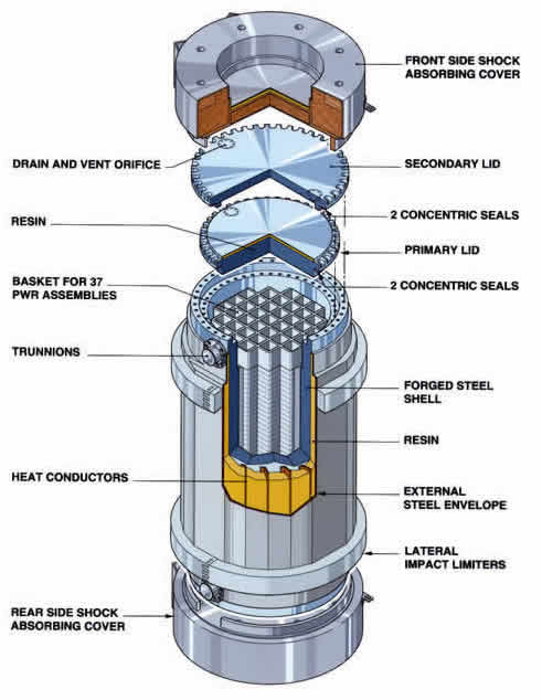
TN24 cask produced by Orano TN (formerly Areva TN)
In the USA the Nuclear Regulatory Commission noted about 2013: “Over the last 40 years, thousands of shipments of commercially generated spent nuclear fuel have been made throughout the United States without causing any radiological releases to the environment or harm to the public.” Most of these shipments are between different power plants owned by the same utility, so as to share storage space for used fuel.
Holtec produces a number of Type B shipping packages or casks. Its HI-STAR 100 is a high-capacity system which is engineered to accept one sealed multi-purpose canister (MPC) containing a 68-cell fuel basket for BWR fuel or a 32-cell fuel basket for PWR fuel. It has been licensed since 1998 for transport (horizontal) and storage (vertical, on end). The MPC containing the fuel can be transferred to HI-STORM 100 storage systems on an ISFSI pad or below ground surface, exchanging one overpack for another which is engineered for maximum shielding. The MPC is loaded under water. In 2018 Holtec sold its HI-STAR 100MB casks to CNNC Everclean in China – a medium-weight version of the cask for bare fuel or fuel in canisters.
Orano has a range of Type B transport casks for used fuel, its newest ones being TN112 and TN117. Its older TN12/2 cask designed for used fuel has been adapted for fresh MOX fuel, and holds 12 PWR fuel assemblies or 32 BWR ones. It is robust, with shock-absorbing covers at each end. Each year Orano moves about 200 casks with used fuel and about 20 with vitrified HLW. Fresh MOX fuel and vitrified HLW use different casks than for used fuel. Used MOX fuel requires greater neutron shielding, such as provided by the TN112 cask, which has a double containment barrier and can also take 50 kW heat load. It has lead shielding with steel, while the older one is simply forged steel. Both have resin compound shielding. They are both loaded under water.
Holtec’s HI-STAR 80 cask, a multi-layered steel cylinder which holds 12 PWR or 32 BWR high-burnup used fuel assemblies (above 45 GWd/t) which have had cooling times as short as 18 months. The HI-STAR 60 cask can transport 12 PWR used fuel assemblies. The HI-STAR 180 was the first one licensed to transport high burn-up fuel, and holds 32 or 37 PWR used fuel assemblies. The HI-STAR 190 cask has 38 kW heat load capacity and one version is to be used domestically in Ukraine for PWR fuel*. It is envisaged as the main used fuel transport to central storage or disposal sites in the USA and is promoted as a universal transport cask. It will accommodate all types of spent fuel MPCs used in the USA (namely Orano, Pacific Nuclear, Vectra, NAC, Sierra Nuclear, BNFL Solutions, and Westinghouse). All HI-STAR casks have an aluminium impact limiter at each end, making the whole unit about 7 metres long.
* The initial licence by the US Nuclear Regulatory Commission covers transport of Holtec's MPC-37 canisters for PWR fuel and MPC-89 canisters for BWR fuel, while Ukraine's SNRIU has certified VVER canisters MPC-31 and MPC-85 for transport in the cask.
In Russia, TUK (transportation packaging set) casks are used to transport used nuclear fuel. Several TUK-13 casks fit into a container or TK carrier for rail transport, each cask holding 12 VVER fuel assemblies (about 6 tonnes). A larger TUK-1410 cask from the Federal Centre for Nuclear & Radiation Safety has now been licensed to replace the older model for VVER-1000 fuel, both in Russia and from overseas. Each weighs over 100 tonnes, holds 18 VVER fuel assemblies weighing 9 tonnes in a removable canister, and is designed for hotter fuel – up to 36 kW heat load. The TUK-14 series is also more heavily shielded, and can carry VVER-1200 fuel. It fits a TK-U-141 railway carrier.
OMZ subsidiary Izhorskiye Zavody has completed the prototype of a new generation of container for the transport and storage of used nuclear fuel from VVER-1000 and VVER-1200 reactors. The TUK-151 container is a thick-walled 2.5m diameter vessel with a sealed lid, a length of about 6 metres and a laden weight of 116 tonnes. Unlike the TUK-13 container design, the TUK-151 is not made of stainless steel, but has a low alloy steel-plated interior surface that offers "superior strength" and resistance to fracturing at low temperatures under dynamic loads.
In the UK, 47- or 53-tonne rectangular Type B flasks have long been used to transport Magnox and AGR fuel, which is held in internal skips. In Sweden, more than 80 large transport casks are shipped annually to a central interim waste storage facility called CLAB. Each 80-tonne cask has steel walls 30 cm thick and holds 17 BWR or 7 PWR fuel assemblies. The used fuel is shipped to CLAB after it has been stored for about a year at the reactor, during which time heat and radioactivity diminish considerably. Both these systems are for transport only, not storage.
Spain's ENSA supplied an ENUN 24P dual-purpose cask to CNNC Everclean in China in 2018, for transporting used fuel from Daya Bay inland to the Lanzhou Nuclear Fuel Complex in Gansu province for storage. The ENUN cask is licensed for high burn-up fuel, to 57 GWd/tU and, with an external diameter of only 3.3 m, it holds 24 PWR fuel assemblies. The ENUN 32P cask has been used in Spain. CNNC Everclean has also bought Holtec HI-STAR 100MB casks and NAC-STC casks. China is now producing its own 100-tonne Longzhou-CNSC cask which holds 21 PWR fuel assemblies.
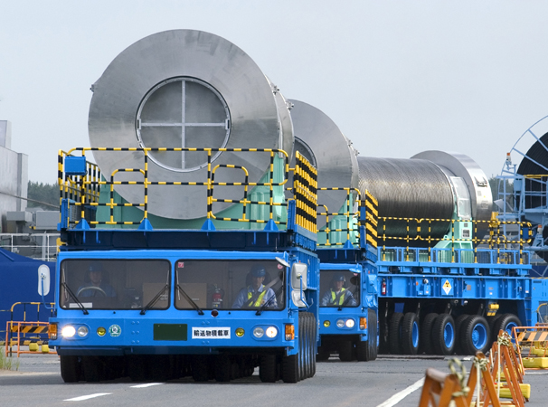
Road transport of used nuclear fuel, Japan. Image: Nuclear Fuel Transport Ltd.
Other ideas for disposal
Numerous options for long-term nuclear waste management have been considered in the past. The table below highlights a number of these.
| Ideas | Examples | |
| Long-term above ground storage |
|
|
| Disposal in outer space (proposed for wastes that are highly concentrated) |
|
|
| Rock-melting (proposed for wastes that are heat-generating) |
|
|
| Disposal at subduction zones |
|
|
| Sea disposal |
|
|
| Sub seabed disposal |
|
|
| Disposal in ice sheets (proposed for wastes that are heat-generating) |
|
|
| Deep well injection (for liquid wastes) |
|
|
Long-term above ground storage
Above ground storage is normally considered an interim measure for the management of radioactive waste (see section above on Interim waste storage). But it has, in the past, been considered as a disposal option. France investigated it for HLW within the framework of the 1991 law on research into radioactive waste management (Act No 91-1381 of 30 December 1991, also known as the 'Bataille Act' after the name of its proposer), but not as a means of final disposal. However, controlled surface storage over longer time periods (greater than a couple of hundred of years) has also been suggested as a long-term waste management option.
Long-term above ground storage involves specially constructed facilities at the Earth's surface that would be neither backfilled nor permanently sealed. Hence, this option would allow monitoring and retrieval at any time without excessive expenditure.
Suggestions for long-term above ground storage broadly fall into two categories:
- Conventional stores of the type currently used for interim storage, which would require replacement and repackaging of waste every 200 years or so.
- Permanent stores that would be expected to remain intact for tens of thousands of years. These structures are often referred to as 'Monolith' stores or 'Mausoleums'.
The latter category of store is derived from the principle of 'guardianship', where future generations continue to monitor and supervize the waste.
Both suggestions would require information to be passed onto future generations, leading to the question of whether the stability of future societies could be ensured to the extent necessary to continue the required monitoring and supervision.
No country is currently planning to implement long-term (i.e. greater than a few hundred years) above ground storage. However, France is investigating long-term interim storage, but not necessarily above ground.
Long-term above ground storage has been considered as part of the range of management concepts in Switzerland by EKRA (Expert Group on Disposal Concepts for Radioactive Waste). EKRA observed that it was unclear what additional steps would be necessary to show how the long-term above ground storage concept could be brought to the state of development comparable with that of geological disposal, and it recommended geological disposal as the preferred option.
Disposal in outer space
The objective of this option is to remove the radioactive waste from the Earth, for all time, by ejecting it into outer space. The waste would be packaged so that it would be likely to remain intact under most conceivable accident scenarios. A rocket or space shuttle would be used to launch the packaged waste into space. There are several ultimate destinations for the waste which have been considered, including directing it into the Sun.
The high cost means that such a method of waste disposal could only be appropriate for separated HLW – i.e. long-lived highly radioactive material that is relatively small in volume – rather than spent fuel. The question was investigated in the USA by NASA in the late 1970s and early 1980s. Because of the high cost of this option and the safety aspects associated with the risk of launch failure, it was abandoned.
Rock melting
The deep rock melting option involves the melting of wastes in the adjacent rock. The idea is to produce a stable, solid mass that incorporates the waste, or encases the waste in a diluted form (i.e. dispersed throughout a large volume of rock), and that cannot easily be leached and transported back to the surface. This technique has been mainly suggested for heat-generating wastes such as vitrified HLW (see information paper on Treatment and Conditioning of Nuclear Wastes) and host rocks with suitable characteristics to reduce heat loss.
The HLW in liquid or solid form could be placed in an excavated cavity or a deep borehole. The heat generated by the wastes would then accumulate resulting in temperatures great enough to melt the surrounding rock and dissolve the radionuclides in a growing sphere of molten material. As the rock cools it would crystallize and incorporate the radionuclides in the rock matrix, thus dispersing the waste throughout a larger volume of rock. There are some variations of this option in which the heat-generating waste would be placed in containers and the rock around the container melted. Alternatively, if insufficient heat is generated the waste would be immobilized in the rock matrix by conventional or nuclear explosion.
Rock melting has not been implemented anywhere for radioactive waste. There have been no practical demonstrations of the feasibility of this option, apart from laboratory studies of rock melting. In the late 1970s and early 1980s, the rock melting option at depth was taken forward to the engineering design stage. This design involved a shaft or borehole which led to an excavated cavity at a depth of 2.5 kilometres. It was estimated, but not demonstrated, that the waste would be immobilized in a volume of rock 1000 times larger than the original volume of waste.
Another early proposal was for the heat-generating wastes to be emplaced in weighted, heat-resistant containers such that they would melt the underlying rock, allowing them to move downwards to greater depths with the molten rock solidifying above. This proposed option resembles similar self-burial methods proposed for disposal of HLW in ice sheets (see section below on Disposal in ice sheets).
In the 1990s there was renewed interest in this option, particularly for the disposal of limited volumes of specialized HLW (particularly plutonium) in Russia and in the UK. A scheme was proposed in which the waste content of the container, the container composition, and the placement layout would be designed to preserve the container and prevent the wastes becoming incorporated in the molten rock. The host rock would be only partially melted and the container would not move to greater depths.
Russian scientists have proposed that HLW, particularly excess plutonium, could be placed in a deep shaft and immobilized by nuclear explosion. However, the major disturbance to the rock mass and groundwater by the use of nuclear explosions, as well as arms control considerations, has led to the general rejection of this option.
Disposal at subduction zones
Subduction zones are areas where one denser section of the Earth's crust is descending beneath another lighter, more buoyant section. The movement of one section of the Earth's crust below another is marked offshore by a trench, and earthquakes commonly occur adjacent to the inclined contact between the two plates. The edge of the overriding plate is crumpled and uplifted to form a mountain chain parallel to the trench. Deep sea sediments may be scraped off the descending slab and incorporated into the adjacent mountains. As the oceanic plate descends into the hot mantle, parts of it may begin to melt. The magma thus formed migrates upwards, some of it reaching the surface as lava erupting from volcanic vents. The idea for this option would be to dispose of wastes in the trench region such that they would be drawn deep into the Earth.
Although subduction zones are present at a number of locations across the Earth's surface, they are geographically very restricted. Not every waste-producing country would be able to consider disposal to deep-sea trenches, unless international solutions were sought. However, this option has not been implemented anywhere and, as it is a form of sea disposal, it is therefore not permitted by international agreements.
Sea disposal
Disposal at sea involves radioactive waste being dropped into the sea in packaging designed to either: implode at depth, resulting in direct release and dispersion of radioactive material into the sea; or sink to the seabed intact. Over time the physical containment of containers would fail, and remaining radionuclides would be dispersed and diluted in the sea. Further dilution would occur as the radionuclides migrated from the disposal site, carried by currents. The amount of radionuclides remaining in the seawater would be further reduced both by natural radioactive decay, and by the removal of radionuclides to seabed sediments by the process of sorption.
This method is not permitted by a number of international agreements.
The application of the sea disposal of LLW and ILW has evolved over time from being a disposal method that was actually implemented by a number of countries, to one that is now banned by international agreements. Countries that have at one time or another undertaken sea disposal using the above techniques include Belgium, France, Germany, Italy, the Netherlands, Sweden, Switzerland, and the UK, as well as Japan, South Korea, and the USA. This option has not been implemented for HLW.
Sub-seabed disposal
For the sub-seabed disposal option, radioactive waste containers would be buried in a suitable geological setting beneath the deep ocean floor. This option has been suggested for LLW, ILW, and HLW. Variations of this option include:
- A repository located beneath the seabed. The repository would be accessed from land, a small uninhabited island, or from an offshore structure.
- Burial of radioactive waste in deep ocean sediments.
Sub-seabed disposal has not been implemented anywhere and is not permitted by international agreements.
The disposal of radioactive wastes in a repository constructed below the seabed has been considered by Sweden and the UK. In comparison to disposal in deep ocean sediments, if it were desirable the repository design concept could be developed so as to ensure that future retrieval of the waste remained possible. The monitoring of wastes in such a repository would also be less problematic than for other forms of sea disposal.
Burial of radioactive waste in deep ocean sediments could be achieved by two different techniques: penetrators or drilling placement. The burial depth of waste containers below the seabed can vary between the two methods. In the case of penetrators, waste containers could be placed about 50 metres into the sediments. Penetrators weighing a few tonnes would fall through the water, gaining enough momentum to embed themselves into the sediments. A key aspect of the disposal of waste to seabed sediments is that the waste is isolated from the seabed by a thickness of sediments. In 1986, some confidence in this process was obtained from experiments undertaken at a water depth of approximately 250 metres in the Mediterranean Sea. The experiments provided evidence that the entry paths created by penetrators were closed and filled with remoulded sediments of about the same density as the surrounding undisturbed sediments.
Wastes could also be placed using drilling equipment based on the techniques in use in the deep sea for about 30 years. By this method, stacks of packaged waste would be placed in holes drilled to a depth of 800 metres below the seabed, with the uppermost container about 300 metres below the seabed.
In the 1980s, the feasibility of the disposal of HLW in deep ocean sediments was investigated and reported by the Organization for Economic Co-operation and Development (OECD). For this concept, radioactive waste would be packaged in corrosion-resistant containers or glass, which would be placed beneath at least 4000 metres of water in a stable, deep seabed geology chosen both for its slow water flow and for its ability to retard the movement of radionuclides. Radionuclides that are transported through the geological media, to emerge at the bottom of the seawater volume, would then be subjected to the same processes of dilution, dispersion, diffusion, and sorption that affect radioactive waste disposed of at sea (see section above on Sea Disposal). This method of disposal therefore provides additional containment of radionuclides when compared with the disposal of wastes directly to the seabed.
Disposal in ice sheets
Since 1980 there has been no significant consideration of this option.
Containers of heat-generating waste would be placed in stable ice sheets such as those found in Greenland and Antarctica. The containers would melt the surrounding ice and be drawn deep into the ice sheet, where the ice would refreeze above the wastes creating a thick barrier. Although disposal in ice sheets could be technically considered for all types of radioactive wastes, it has only been seriously investigated for HLW, where the heat generated by the wastes could be used to achieve self-burial within the ice by melting.
The option of disposal in ice sheets has not been implemented anywhere. It has been rejected by countries that have signed the 1959 Antarctic Treaty or have committed to providing a solution to their radioactive waste management within their national boundaries.
Deep well injection (liquid)
This approach involves the injection of liquid radioactive waste directly into a layer of rock deep underground that has been chosen because of its suitable characteristics to trap the waste (i.e. minimize any further movement following injection).
In order to achieve this there are two geological prerequisites. There must be a layer of rock (injection layer) with sufficient porosity to accommodate the waste and with sufficient permeability to allow easy injection (i.e. act like a sponge). Above and below the injection layer there must be impermeable layers that act as a natural seal. Additional benefits could be provided from geological features that limit horizontal or vertical migration. For example, injection into layers of rock containing natural brine groundwater. This is because the high density of brine (salt water) would reduce the potential for upward movement.
Direct injection could in principle be used on any type of radioactive waste provided that it could be transformed into a solution or slurry (very fine particles in water). Slurries containing a cement grout that would set as a solid when underground could also be used to help minimize movement of radioactive waste.
Direct injection has been implemented in Russia and the USA.
In 1957 extensive geological investigations started in Russia for suitable injection layers for radioactive waste. Three sites were found, all in sedimentary rocks. At Krasnoyarsk-26 and Tomsk-7 injection takes place into two porous sandstone beds capped by clays at depths up to 400 metres. Whereas at Dimitrovgrad injection has now stopped, but took place into sandstone and limestone formations at a depth of 1400 metres. In total, some tens of millions of cubic metres of LLW, ILW and HLW have been injected in Russia.
In the USA, direct injection of about 7500 cubic metres of LLW as cement slurries was undertaken during the 1970s at a depth of about 300 metres over a period of 10 years at the Oak Ridge National Laboratory, Tennessee. It was abandoned because of uncertainties over the migration of the grout in the surrounding fractured rocks (shales). In addition a scheme involving HLW injection into crystalline bedrock beneath the Savannah River Site in South Carolina was abandoned before it was implemented due to public concerns.
Tenorm
Radioactive material is produced or collected as a waste product from the oil and gas industry and generally referred to as 'technologically enhanced naturally occurring radioactive material' (Tenorm)m. In oil and gas production, radium-226, radium-228 and lead-210 are deposited as scale in pipes and equipment in many parts of the world. Published data show radionuclide concentrations in scales up to 300,000 Bq/kg for Pb-210, 250,000 Bq/kg for Ra-226 and 100,000 Bq/kg for Ra-228. However, scrap steel from gas plants may be recycled if it has less than 500,000 Bq/kg (0.5 MBq/kg) radioactivity (the exemption level)n. This level however is 1000 times higher than the clearance level for recycled material (both steel and concrete) from the nuclear industry, where anything above 500 Bq/kg may not be cleared from regulatory control for recycling and must be disposed of, usually as intermediate-level waste.
The largest Tenorm waste stream is coal ash, with 280 million tonnes arising globally each year, and carrying uranium-238 and all its non-gaseous decay products, as well as thorium-232 and its progeny. This is usually just buried.
The double standard means that the same radionuclide, at the same concentration, can either be sent to deep disposal as waste (if scrap from the nuclear industry) or released for use in building materials (if contained in fly ash or recycled steel from oil/gas production).
Notes & References
a. In the USA, the Yucca Mountain site in Nevada has been chosen to site a deep geologic repository for disposal of high-level radioactive waste, but the project is beset by political interference. A licence application to construct the repository was submitted to the US Nuclear Regulatory Commission (NRC) by the US Department of Energy (DOE) on 3 June 2008. However, soon after entering office, the Barack Obama administration decided to cancel the project. Later, in June 2010, the NRC's Atomic Safety and Licensing Board (ASLB) denied the DOE's motion to withdraw the licence application. The order by the ASLB noted the 1982 Nuclear Waste Policy Act (NWPA) "does not give the Secretary the discretion to substitute his policy for the one established by Congress in the NWPA." The ASLB concluded: "Unless Congress directs otherwise, DOE may not single-handedly derail the legislated decision-making process by withdrawing the Application. DOE’s motion must therefore be denied." [Back]
b. See the Near Surface Disposal page in the Waste Technology Section of the IAEA website (www.iaea.org) for further information. [Back]
c. A brochure on SFR, the final repository for radioactive operational waste, is available from SKB. [Back]
d. Information on the Finnish repositories for operating waste can be found on Posiva's website. [Back]
e. The Swedish repository programme is described in various SKB publications. Information on the Finnish repositories for operating waste can be found on Posiva's website. [Back]
f. See Assessment of Disposal Options for DOE-Managed High-Level Radioactive Waste and Spent Nuclear Fuel (October 2014), and Disposal options for disused radioactive sources, International Atomic Energy Agency, Technical reports series, STI/DOC/010/436 (July 2005; ISBN: 9201003056). [Back]
g. The SAFIR 2 report - which presented scientific and technical research on the possible final disposal of high-level and/or long-lived radioactive waste in deep clay layers. [Back]
h. The Swiss National Cooperative for the Disposal of Radioactive Waste (Nagra) has proposed three siting regions for the high-level waste repository. See the Nagra website (www.nagra.ch) for information on management of nuclear waste in Switzerland; in particular Opalinus Clay Project: Demonstration of feasibility of disposal (“Entsorgungsnachweis”) for spent fuel, vitrified high-level waste and long-lived intermediate-level waste - Summary Overview, Nagra (December 2002). [Back]
i. The website of the Department of Energy's Office of Civilian Radioactive Waste Management (www.ocrwm.doe.gov) stated: "The President has made clear that Yucca Mountain is not an option for waste storage." (see also Note a above). [Back]
j. The website of the Waste Isolation Pilot Plant is at www.wipp.energy.gov. [Back]
k. Nirex was incorporated into the Radioactive Waste Management Directorate of the UK's Nuclear Decommissioning Authority (NDA) in 2007 and no longer exists as a separate entity. The Nirex Phased Disposal Concept is outlined in the Introductory Leaflet What is the Nirex Phased Disposal Concept?, Nirex (2002). [Back]
l. See Assessment of Disposal Options for DOE-Managed High-Level Radioactive Waste and Spent Nuclear Fuel (October 2014), and Disposal options for disused radioactive sources, International Atomic Energy Agency, Technical reports series, STI/DOC/010/436 (July 2005; ISBN: 9201003056). [Back]
m. In the UK, much of these wastes are exempt from the need for their disposal to be authorized under the UK's Radioactive Substances Act 1993 because of their low levels of radioactivity. However, some of the wastes are of higher activity and there are currently a limited number of disposal routes available. This includes re-injection back into the borehole (i.e. well-head), which is authorized by the UK's Environment Agency. [Back]
n. The main radionuclide in scrap from the oil and gas industry is radium-226, with a half-life of 1600 years as it decays to radon. [Back]
General sources
S. Walker et al, Idaho National Engineering Laboratory, An Overview of In Situ Waste Treatment Technologies, presented at the Spectrum '92 Conference, Boise, Idaho (August 1992)
Malcolm B. Cooper, Naturally Occurring Radioactive Materials (NORM) in Australian Industries - Review of Current Inventories and Future Generation, ERS-006, A Report prepared for the Radiation Health and Safety Advisory Council (Revision of September 2005)
Geological Waste Disposal page in the Waste Technology Section of the IAEA website
Fact Sheet Understanding the potential for volcanoes at Yucca Mountain, Office of Civilian Radioactive Waste Management, US Department of Energy, 2002
Deep Borehole Disposal of Nuclear Waste: Final Report, Sandia Report SAND2012-7789, Sept 2012
Assessment of Disposal Options for DOE-Managed High-Level Radioactive Waste and Spent Nuclear Fuel, October 2014, US DOE
Related information
Radioactive Waste ManagementInternational Nuclear Waste Disposal Concepts
Radioactive Waste – Myths and Realities