Fukushima: Background on Reactors
The Fukushima Daiichi reactors are GE boiling water reactors (BWR) of an early (1960s) design supplied by GE, Toshiba and Hitachi, with what is known as a Mark I containment. Reactors 1-3 came into commercial operation in 1971-76. Reactor power was 460 MWe for unit 1, 784 MWe for units 2-5, and 1100 MWe for unit 6. The fuel assemblies were about 4 m long, and there were 400 in unit 1, 548 in units 2-5, and 764 in unit 6. Each assembly had 60 fuel rods containing the uranium oxide fuel within zirconium alloy cladding. Unit 3 had a partial core of mixed-oxide (MOX) fuel (32 MOX assemblies, 516 LEU). During normal operation they all had a core outlet temperature of 286°C under a pressure of 6930 kPa and with 115-130 kPa pressure in dry containment. The operating pressure was about half that in a PWR. NISA stated maximum design base pressure for reactor pressure vessels (RPVs) was 8240 kPa at 300°C, and for the primary containment vessel (PCV) it was about 500 kPa*.
* NISA gives 430 kPa for unit 1 and 380 kPa for 2-3 at 140°C as 'maximum', apparently gauge pressure, so add 101 for absolute: 530 and 480 kPa. Before venting, unit 1 RPV got to 900 kPa and PCV to 850 kPa early on 12 March 2011.
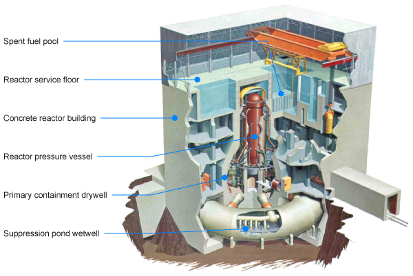
The BWR Mark I has a primary containment system comprising a free-standing bulb-shaped drywell of 30 mm steel backed by a reinforced concrete shell, and connected to a torus-shaped wetwell beneath it containing the suppression pool (with 3000 m3 of water in units 2-5). The drywell, also known as the primary containment vessel (PCV), contains the reactor pressure vessel (RPV). For simplicity, the term 'dry containment' is used here. The water in the suppression pool acts as an energy-absorbing medium in the event of an accident. The wetwell is connected to the dry containment by a system of vents, which discharge under the suppression pool water in the event of high pressure in the dry containment. The function of the primary containment system is to contain the energy released during any loss of coolant accident (LOCA) of any size reactor coolant pipe, and to protect the reactor from external assaults. The Japanese version of the Mark I is slightly larger than the original GE version.
During normal operation, the dry containment atmosphere and the wetwell atmosphere are filled with inert nitrogen, and the wetwell water is at ambient temperature. A small amount of hydrogen is routinely formed by radiolytic decay of water, and this is normally dealt with by recombiners in the containment vessel. They would be insufficient for countering major hydrogen formation due to oxidation of zirconium fuel cladding. Apart from this, at low containment pressures hydrogen and other gases are routinely vented through charcoal filters which trap most radionuclides.
If a LOCA occurs, steam flows from the dry containment (drywell) through a set of vent lines and pipes into the suppression pool, where the steam is condensed. Steam can also be released from the reactor vessel through the safety relief valves and associated piping directly into the suppression pool. Steam will be condensed in the wetwell, but hydrogen and noble gases are not condensable and will pressurise the system, as will steam if the wetwell water is boiling. In this case emergency systems will activate to cool the wetwell, see below. Excess pressure from the wetwell (above 300 kPa) can be vented through the 120 m emission stack via a hardened pipe or into the secondary containment above the reactor service floor of the building. If there has been fuel damage, vented gases will include noble gases (krypton & xenon), iodine and caesium, the latter being scrubbed in some scenarios. Less volatile elements in any fission product release will plate out in the containment. (The later Mark II containments are similar to Mark I, but both are much smaller than the Mark III and those which became standard in PWRs.)
The secondary containment houses the emergency core cooling systems and the used fuel pool. It is not designed to contain high pressure.
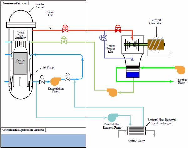
The primary cooling circuit of the BWR takes steam from above the core, in the reactor pressure vessel, to the turbine in an adjacent building. After driving the turbines it is condensed and the water is returned to the pressure vessel by powerful steam-driven pumps. There are also two powerful jet-pump recirculation systems forcing water down around the reactor core and shroud. When the reactor is shut down, the steam in the main circuit is diverted via a bypass line directly to the condensers, and the heat is dumped there, to the sea. In both situations a steam-driven turbine drives the pumps, at least until the pressure drops to about 450 kPa (50 psig), but condenser function depends on large electrically-driven pumps for the seawater which are not backed up by the diesel generators.
In shutdown mode at low pressure, the residual heat removal (RHR) system then operates in a secondary circuit (the RHR is connected into the two jet-pump recirculation circuits), driven by smaller electric pumps, and circulates water from the pressure vessel to RHR heat exchangers which dump the heat to the sea, using external electric pumps in the secondary circuit. This RHR system is fully supported by the diesel generators. Unit 1 had an isolation condenser (IC) for passive core cooling, with reactor steam going to an external condenser, and it needed only DC battery power to operate. Units 2-5 had a reactor core isolation cooling (RCIC) system actuated automatically which can provide make-up water to the reactor vessel (without any heat removal circuit). It was driven by a small steam turbine using steam from decay heat, injecting water from a condensate storage tank or the suppression pool and controlled by the DC battery system. The RCIC systems played a helpful role in units 2&3 until the suppression pool water boiled, to 11 am on 12 March in unit 3, and to 2 pm on the 14th in unit 2.
Then there is an emergency core cooling system (ECCS) as further backup for loss of coolant. It has high-pressure and low-pressure elements. The high pressure coolant injection (HPCI) system in units 1-3 had pumps powered by steam turbines which were designed to work over a wide pressure range. The HPCI drew water from the large torus suppression chamber beneath the reactor as well as a water storage tank, and required only DC battery power. For use below about 700 kPa, there was also a low pressure coolant injection (LPCI) mode through the RHR system but using suppression pool water, and a core spray system, all electrically-driven. All ECCS subsystems require some power to operate valves etc, and the battery backup to generators may provide this.
Beyond these original systems, Tepco in the 1990s installed provision for water injection via the fire extinguisher system through the RHR system (injecting via the jet-pump nozzles) as part of its severe accident management (SAM) countermeasures. Air-cooled diesel generators were installed at Daiichi 2, 4&6 – the last being the only one to survive the tsunami.
The Fukushima reactors had much of their switchgear on the ground floor in the turbine buildings rather than elevated, as at some similar US plants. Also they had control rooms with analogue instrumentation typical of the period, so not only did many instruments fail, but data could not be downloaded and accessed remotely to assist diagnosis and remedial action.
Related information
Fukushima Daiichi AccidentNuclear Power Plants and Earthquakes
Safety of Nuclear Power Reactors
Japan: Nuclear Power